Understanding and controlling the “danger zone” around machinery is a fundamental pilar of industrial safety. It’s important to recognise how humans interact with machines as well as being aware of the reach of a mechanical arm or the rotation of a blade. Combining this knowledge facilitates the specification, design and installation of correctly positioned guarding.
In our experience, when guarding fails to account for real-world usage, the resulting weakness in the system become a primary cause of workplace accidents, ranging from minor cuts to severe crushing injuries.
And of course, UK employers have a legal responsibility for their workers’ safety. Under the Provision and Use of Work Equipment Regulations 1998 (PUWER), identifying and controlling the danger zone is a core principle around which all engineering controls and protective devices are built.
This guide defines exactly what constitutes a danger zone, how to identify it on your machinery installations or in your systems and the compliant solutions required to secure it.
The key takeaways
- The danger zone is any area within or around machinery where a person is exposed to a risk to their health or safety.
- PUWER Regulation 11 places an absolute duty on employers to prevent access to these zones or stop hazardous movement before access is possible .
- Correct safety distances are calculated using strict standards including BS EN ISO 13857 (reach) and BS EN ISO 13855 (stop time).
- Control measures follow a hierarchy: fixed guarding is the preferred option, followed by interlocks and presence-sensing devices.
What Is the Danger Zone?
It’s often assumed that the danger zone is simply the point where a tool meets the workpiece. The regulatory definition is far broader however. According to the Supply of Machinery (Safety) Regulations 2008, a danger zone is defined broadly as “any zone within and/or around machinery in which an exposed person is subject to a risk to his health or safety”. PUWER further clarifies this for workplace safety, focusing on zones where there is a risk of contact with dangerous parts.
This scope encompasses the entire environment influenced by the machine’s energy, including:
- The immediate point of operation where actions such as cutting, punching, or shearing occur.
- Transmission parts such as belts, pulleys, gears and shafts that transmit power.
- Trajectory areas where materials, chips, or broken tools could be ejected.
- Invisible hazards such as extreme heat, radiation, laser light if eye-safe lasers are not deployed, or noise envelopes.
- It is vital to recognise that the danger zone is dynamic. It may shift depending on the machine’s state, presenting different risks during maintenance and cleaning, compared to normal production.
How Are Danger Zones Identified?
To effectively guard a machine, first the danger zones should be mapped by analysing the kinetic energy and specific motions involved. Most hazards fall into three categories of motion:
- Rotating motion: Even smooth shafts can grip clothing or hair. Specific hazards include “in-running nip points” where parts rotate toward each other (e.g. gears or rollers) and entanglement points on couplings or spindles.
- Reciprocating motion: Back-and-forth movement creates trap zones where a moving part approaches a fixed object, creating a crush or shear hazard .
- Transversing motion: Continuous straight-line movement (such as a belt conveyor) creates hazards where a worker may be struck or caught in a pinch point.
Beyond motion, the specific action of the machine defines the nature of the injury risk:
- Cutting and shearing: Bandsaws, circular saws, and hydraulic shears create immediate amputation risks at the point of operation.
- Punching and bending: Power presses and press brakes create severe crush zones where stock is inserted.
- Drilling and boring: The primary danger is entanglement. Rotating spindles and drill bits can catch loose clothing, hair, or gloves, drawing the operator into the machinery.
- Compressing and compacting: Common in balers and compactors, the danger zone is the compression chamber where powerful rams crush material. Serious injuries and even fatalities have occurred here when workers enter the chamber to clear jams.
Legal Duties and Solutions: The Hierarchy of Control
The management of danger zones in the UK is strictly governed by PUWER Regulation 11. This places an absolute duty on employers to prevent access to dangerous parts or stop their movement before a person can reach them.
To achieve this, the Regulation mandates a prescribed “hierarchy of control” that must be followed logically to the extent that it is practicable.
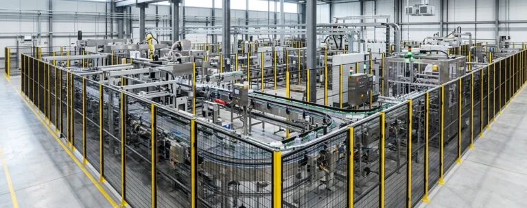
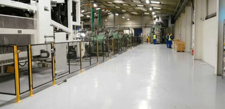
- Fixed enclosing guards. The preferred method is always fixed guards to enclose machinery and provide the highest degree of separation. These are permanent barriers that require tools to remove, making them ideal for hazards requiring infrequent access.
- Other guards and protection devices. Where the need for frequent access makes fixed guards impractical, the Regulation stipulates the use of:
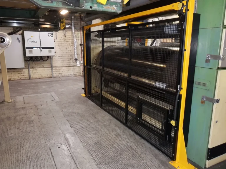
- Interlocked guards. Movable gates connected to a switch that stops the machine when opened. For high-inertia machinery, these must include “guard locking” to prevent opening until motion ceases.
- Adjustable and self-adjusting guards. Essential for manual-feed machinery such as drills or bandsaws. These accommodate the workpiece while restricting the operator’s access to the hazard area.
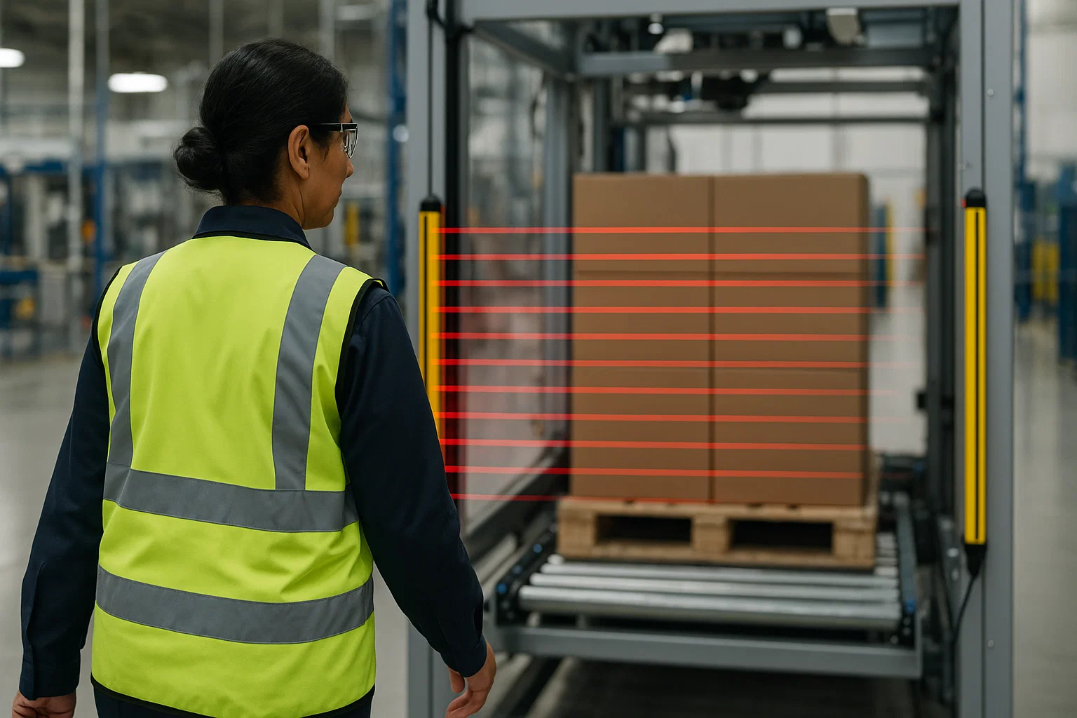
- Presence-sensing systems. Devices such as light curtains, lidar scanners, or pressure mats that detect entry without physical barriers .
- Protection appliances. If specific risks remain after guarding, protection appliances such as jigs or push-sticks must be deployed to keep the operator’s reach outside the danger zone.
- Information, instruction, training, and supervision. Crucially, information, instruction, training, and supervision are the foundation of this hierarchy. These measures are both the final and also the first layer of defence, designed to support and not replace guarding controls. It is vital to ensure that machine operators are not only trained and competent but also strictly adhere to warning signs and respect the installed guarding. Training ensures the guards are used correctly, but it is never a substitute for the guard itself.
Determining Safe Distances
A guard is only effective if it is placed at the correct distance from the hazard. If a guard is too close, an operator might reach through, over it or around it. Industry standards provide the mathematical models to calculate these boundaries.
BS EN ISO 13857: Safety Distances
- This standard establishes values to prevent hazard zones being reached by upper and lower limbs. It considers two main types of access:
- Reaching through: If a guard has openings (e.g. a mesh fence), the distance to the hazard is dictated by the opening size. For example, a slot opening of 20mm requires a safety distance of at least 120mm from the hazard to prevent finger access.
- Reaching over: The standard uses a matrix comparing the “Height of the Hazard” against the “Height of the Guard”. If a hazard is 1200mm high and the guard is 1000mm high, the guard must be placed significantly further back to prevent an operator from reaching over and down into the danger zone.
BS EN ISO 13855: Stop Time Positioning
- For presence-sensing devices such as light curtains, physical distance is calculated based on time. The “safety distance” (S) ensures the machine stops before the operator can reach the hazard. The calculation (S = (K x T) + C) factors in the approach speed of the body (K), the total stopping time of the machine (T), and the intrusion distance (C).
| Height of Hazard Zone (a) [mm] | Height of Protective Structure (b) [mm] | |||||||||
|---|---|---|---|---|---|---|---|---|---|---|
| 1000 | 1200 | 1400 | 1600 | 1800 | 2000 | 2200 | 2400 | 2500 | 2700 | |
| Horizontal safety distance to hazard or danger zone (c) [mm] | ||||||||||
| 2700 | 0 | 0 | 0 | 0 | 0 | 0 | 0 | 0 | 0 | 0 |
| 2600 | 900 | 800 | 700 | 600 | 600 | 500 | 400 | 300 | 100 | 0 |
| 2400 | 1100 | 1000 | 900 | 800 | 700 | 600 | 400 | 300 | 100 | 0 |
| 2200 | 1300 | 1200 | 1000 | 900 | 800 | 600 | 400 | 300 | 0 | 0 |
| 2000 | 1400 | 1300 | 1100 | 900 | 800 | 600 | 400 | 0 | 0 | 0 |
| 1800 | 1500 | 1400 | 1100 | 900 | 800 | 600 | 0 | 0 | 0 | 0 |
| 1600 | 1500 | 1400 | 1100 | 900 | 800 | 500 | 0 | 0 | 0 | 0 |
| 1400 | 1500 | 1400 | 1100 | 900 | 800 | 0 | 0 | 0 | 0 | 0 |
| 1200 | 1500 | 1400 | 1100 | 900 | 700 | 0 | 0 | 0 | 0 | 0 |
| 1000 | 1500 | 1300 | 1000 | 800 | 0 | 0 | 0 | 0 | 0 | 0 |
Risk Assessment as the Foundation
A danger zone cannot be effectively guarded until it’s been mapped it out using a comprehensive risk assessment. A professional PUWER assessment will identify non-compliant danger zones in existing machinery and evaluates whether current guarding meets the strict requirements of Regulation 11.
It is also significant to review these assessments throughout the machine’s lifecycle. Modifications, retrofits, or even changes in the type of material being processed can alter the boundaries of the danger zone, rendering previous guarding inadequate.
Wrap up
The danger zone is at the core of industrial safety management, with a very real line that cannot be crossed without protection. Identifying danger zones is the first step in compliance, but calculating the correct safety distances and selecting the right guarding requires technical expertise and adherence to complex standards such as ISO 13857.
At Safety Systems Technology, we specialise in mapping these risks and designing compliant solutions. From initial PUWER assessments to stop-time testing and guard installation, we ensure your machinery is safe “on the line,” not just on paper.
Frequently Asked Questions
What is the difference between a hazard and a danger zone?
A hazard is the potential source of injury (e.g. a sharp blade or a hot surface). The danger zone is the specific space within or around the machinery where a person is exposed to that hazard.
When can I use a light curtain instead of a physical guard?
Light curtains are suitable when operators need frequent access to the danger zone (e.g. for loading parts) and the machine can stop quickly enough to prevent injury. They are not suitable if the machine ejects materials, as they provide no physical containment.
How often should danger zones be assessed?
Danger zones should be assessed before the machine is commissioned, at regular intervals (as defined by your risk assessment) and importantly, whenever any significant changes or modifications are made to the machine or its operating environment.