Key Takeaways
- Machine guarding hazards rarely arise from a complete lack of protection. They develop as safeguarding degrades, is modified or no longer reflects current operation.
- PUWER Regulation 11 requires prevention of access to dangerous parts based on how machinery operates today, not how it was originally installed.
- Common weaknesses include overlooked in‑running nip points, defeated interlocks, inadequate safety distances and removed guards.
- Environmental exposure and incremental modifications can erode safety margins without obvious warning signs.
- Linking machines into a single system can create new hazards and may trigger additional conformity assessment obligations.
- Safeguarding should be reassessed periodically, particularly after modifications, performance changes or layout alterations.
Serious machinery injuries rarely occur because of a lack of guarding. They usually arise when hazards develop because safeguarding has degraded, been modified, no longer reflects how the equipment actually operates, or was not properly designed in the first place.
Under PUWER 1998 Regulation 11, employers must prevent access to dangerous parts of machinery. That duty applies to equipment as it functions today, not as it was first commissioned.
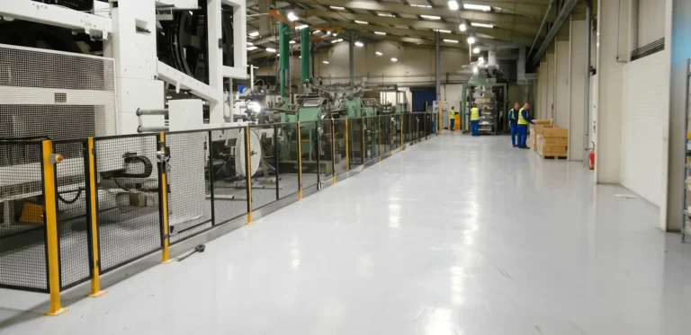
Across diverse industrial sectors and operating environments, safeguarding weaknesses tend to fall into eight recurring categories. These are not dramatic oversights, but incremental gaps that persist unnoticed until something goes wrong.
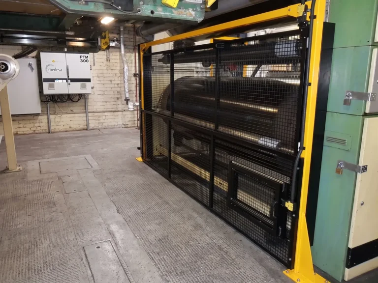
In Running Nip Points Beyond the Obvious Location
The primary nip point at a belt and pulley junction is usually identified and guarded during installation.
Drive systems rarely consist of a single hazard. Chain and sprocket interfaces, rack and pinion assemblies, rotating shafts passing close to fixed framework and conveyor return rollers can all present entrapment risks. These secondary points may not have been prominent during the original assessment, particularly if access was limited or the layout has since evolved.
Safeguarding strategies can focus on the most visible hazards while less obvious transmission points remain accessible. The risk is not created by a complete but a partial absence of guarding. This is particularly the case if the way the machine is used and maintained has changed.
PUWER requires prevention of access wherever dangerous parts exist, not only at the primary point of operation.
Guards Removed for Maintenance and Never Replaced
Guards are frequently removed for entirely legitimate reasons such as cleaning, inspection and fault finding. Problems begin when repeated temporary removal becomes embedded practice.
In busy environments, a guard that needs frequent removal can be perceived as obstructive. Refitting may be delayed and then operating without that barrier becomes normalised. The original design intent is steadily eroded.
This rarely reflects deliberate disregard but more often a drift towards reliance on familiarity and experience.
The machine still appears familiar and the risk feels unchanged even through the physical separation between people and moving parts has been reduced.
A more subtle variation occurs when guards are replaced but not secured using all original fixings. Although many designs specify captive fasteners to prevent loss, these are not always present or maintained. Over time, bolts or screws may go missing and panels refitted with fewer attachment points than intended. The guard remains in position, but its rigidity and resistance to movement or vibration may be reduced.
It may be that the machine is now used more often or for a greater volume of production and/or maintenance. Regardless, PUWER requires guarding to be in place during operation. If the safeguarding strategy does not accommodate routine access needs, the safeguarding approach should be revaluated and alternatives considered.
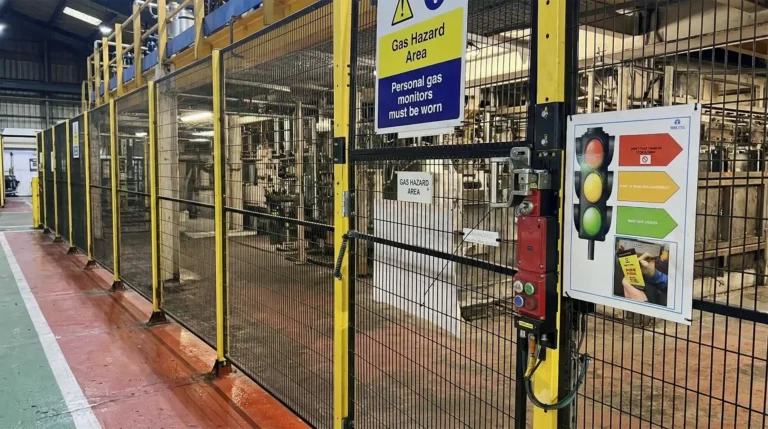
Interlock Tampering and Defeat
Interlocked guards are intended to allow access where necessary while maintaining protection. When selected and positioned correctly, they provide a controlled balance between safety and usability.
Where they are inexpertly integrated into workflow, however, they can become a source of frustration. Small delays in cycle time or awkward access points can encourage informal workarounds. A spare actuator left in a switch or a magnetic sensor overridden may begin as a temporary solution and then overtime become routine.
As we’ve previously suggested, this isn’t usually about a disregard for safety, but a signal that the safeguarding design does not align with operational reality.
BS EN ISO 14119 addresses the selection and positioning of interlocking devices. These devices form part of the machine control system. Under PUWER Regulation 18, control systems must not create additional risk.
Under PUWER Regulation 18, control systems must not create additional risk. A system that is easily defeated in day to day operation is unlikely to remain effective or compliant as equipment ages.
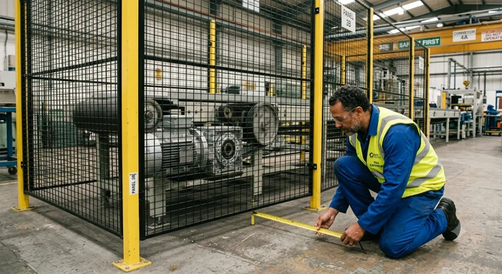
Inadequate Safety Distances
Even if a guard is installed it can be ineffective, either because the safety distances were incorrectly calculated or because these have changed. Similarly, mesh or aperture sizes that were once considered appropriate may allow access if standards are not properly applied. A panel that appears robust may still permit fingers or hands to reach hazardous parts.
BS EN ISO 13857 provides minimum distances to prevent reaching over or through protective structures. These distances are linked to measured stopping performance. If stop times increase due to wear, replacement parts or higher operating speeds, the original calculation may no longer be valid.
The issue is rarely obvious on visual inspection but becomes apparent through measurement. Where dimensional verification has not been revisited for several years, guarding may no longer perform as intended.
Unexpected Restart and Inadequate Run Down Time
Machinery does not always become safe the moment a stop button is pressed. Heavy rotating components such as fans, flywheels and drums can continue moving after power is removed. For this reason stop time testing is used when guarding is positioned. However, the duration of this residual motion can change gradually as components wear or are replaced. The system may not look as if it’s changed but the safety margin has narrowed.
PUWER Regulation 19 and BS EN 60204 1 require appropriate isolation and control of energy. Without periodic validation of stopping performance, safeguarding may be relying on assumptions that are no longer accurate.
Environmental and Process Conditions
Guarding is subject to the same environmental and process pressures as the machinery it protects. In food and beverage production, aggressive cleaning chemicals can corrode metal components and degrade seals. In pharmaceutical settings, repeated washdown cycles may affect plastics and viewing panels. In heavy industry, heat and particulates can distort structures and contaminate sensors.
In some operations, very high or very low process temperatures are present behind fixed guards. Even where mechanical access is adequately controlled, hot surfaces, heated pipework or cryogenic components may present a burn or cold contact hazard in their own right. Safeguarding strategies should therefore consider thermal risk alongside mechanical entrapment, particularly where access is required for cleaning, inspection or maintenance.
The deterioration of machine guarding equipment is usually gradual. A viewing panel becomes less transparent. An interlock alignment shifts slightly. A metal frame shows early signs of corrosion. Individually these changes may appear minor. In combination, and if left unchecked, they can compromise the protective function.
PUWER requires equipment to be maintained in efficient working order. Without periodic inspection that considers environmental exposure and process conditions, safeguarding may no longer perform as intended.
PUWER Regulation 19 and BS EN 60204 1 require appropriate isolation and control of energy. Without periodic validation of stopping performance, safeguarding may be relying on assumptions that are no longer accurate.
Hidden Access Points at the Rear, Sides and Underside
Risk assessments often concentrate on the primary operator interface, which is understandable since it is where interaction is most visible and frequent.
However, hazards are not confined to the front of a machine. Danger zones include maintenance hatches, cable routing apertures, feed openings and underside access points, all of which can provide unintended access to hazardous components and areas. As layouts change or machines are repositioned, these access points may become more exposed. In some installations, perimeter guarding is raised above floor level to allow for cleaning, drainage or washdown. While operationally convenient, this can create access beneath the machine frame. Return rollers, drive components or moving belts may then be reachable from a low position that was not fully considered in the original assessment.
Assumptions about restricted access can become less reliable over the years. A thorough safeguarding assessment considers the complete machine footprint.
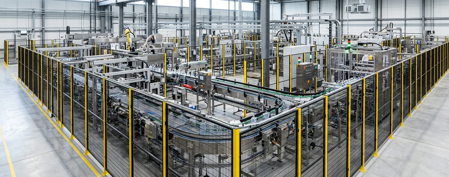
Modifications, Replacement Parts and Complex Assemblies
Very few production systems remain unchanged. Over time modifications or updates such as the replacement of braking components or drives can affect stopping performance. Changes to tooling or material can alter hazard zones. These variations accumulate and move the system beyond the scope of its original assessment.
When conveyors, spiral lifts or pallet wrappers are linked to function as a single system, they may form a complex assembly. Under the Supply of Machinery Safety Regulations 2008, such an assembly can be treated as a new machine in its own right. Conformity assessment obligations may therefore arise at system level, not just at component level.
Individual CE or UKCA marking does not automatically confirm that the integrated system remains compliant. Emergency stop circuits, interlock devices and transfer points must operate effectively across the complete system. The points where machines connect often create new nip or entrapment hazards that were not present when each machine operated independently.
Compliance is not fixed at the point of commissioning. It must reflect the machinery as it operates today.
Wrap Up
In many facilities, machine guarding was properly designed and installed at the outset. As production demands change, components are replaced, system performance deteriorates, equipment may be linked together, access requirements alter, environmental conditions take their toll. Gradually, the original safeguarding assumptions become less reliable. The common factor across all eight hazards is change over time.
In other instances, guarding may have been poorly specified, designed or installed in the first place and was never truly effective from the outset.
PUWER requires prevention of access to dangerous parts under current operating conditions. That obligation cannot be met through historic documentation alone. It depends on measurement, verification and periodic reassessment.
Effective machine guarding is not a static feature of a production line. It is an ongoing engineering process. When safeguarding evolves in step with the machinery it protects, it supports both safety and productivity.
Review your current safeguarding arrangements and any recent modifications. If you would like an independent perspective, get in touch.
Frequently Asked Questions
What are the most common machine guarding hazards?
Common machine guarding hazards include in running nip points, defeated or bypassed interlocks, inadequate safety distances, guards removed for maintenance, environmental degradation and hazards introduced through system modifications.
What does PUWER require for machine guarding?
PUWER Regulation 11 requires employers to prevent access to dangerous parts of machinery. Guarding must remain effective under current operating conditions and be maintained in efficient working order.
How can safety distances become non compliant?
Safety distances are typically calculated using standards such as BS EN ISO 13857 and may depend on stopping performance. If stopping times increase or operating speeds change, existing guarding distances may no longer provide adequate protection.
When does linking machines create new compliance obligations?
When separate machines are connected to function as a single system, they may form a complex assembly. Under the Supply of Machinery Safety Regulations 2008, this can trigger new conformity assessment requirements at system level.
Why are incremental changes such a risk?
Small changes such as component wear, replacement parts, increased throughput or layout adjustments can gradually reduce safeguarding effectiveness. These changes may not be obvious but can narrow the safety margin over time.
How often should machine guarding be reviewed?
There is no fixed interval prescribed in PUWER. However, guarding should be reviewed after modifications, performance changes, incidents or significant maintenance work, and periodically as part of routine safety management.